Constant Product Withdrawal According to the FIFO Principle

Do you want to dose mass flow according to the First In First Out principle? Then it is essential that the product column above the dosing screw descends evenly. Our MFS dosing screws process the same volume with every rotation. This gives you full control over the mass flow. Dosing with the precision of Klinkenberg — guaranteed success!
Massastroom doseren
Massastroom doseren

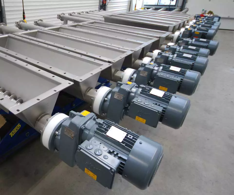
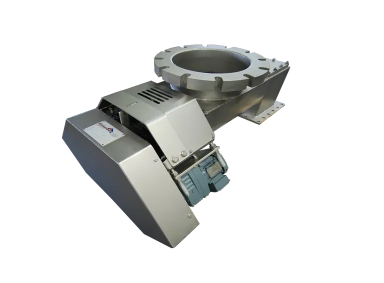
Design and functionality of discharge screws for mass flow dosing

Design principles for consistent mass flow with FIFO discharge screws

When designing a discharge screw, also known as an extraction screw for mass flow dosing, an even capacity distribution across the entire surface of the hopper or silo outlet is crucial. This contributes to a consistent mass flow and prevents operational issues such as bridging, channeling, or irregular product discharge.

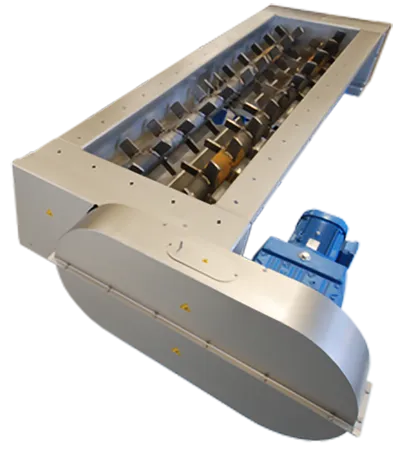
Uniform product extraction is especially important in processes that require continuous withdrawal of bulk materials, such as in vertical heat exchangers or cooling towers. In such applications, it is essential that the product is discharged according to the First In, First Out (FIFO) principle, ensuring uniform thermal or chemical processing.

By applying one or a combination of these design adjustments, a stable and controlled product discharge is achieved — essential for processes where consistent mass flow and FIFO material extraction are desired.

Need technical advice or want to discuss the possibilities?

To achieve this uniform extraction, several factors must be considered in the design of the discharge screw:
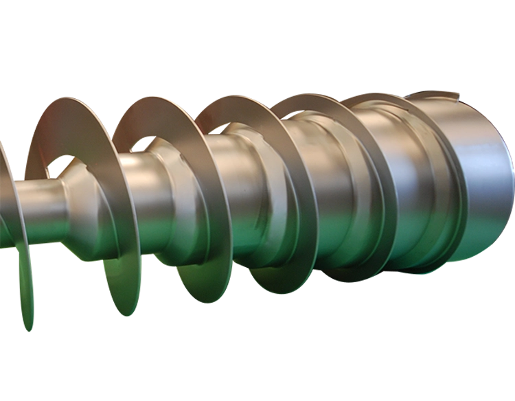
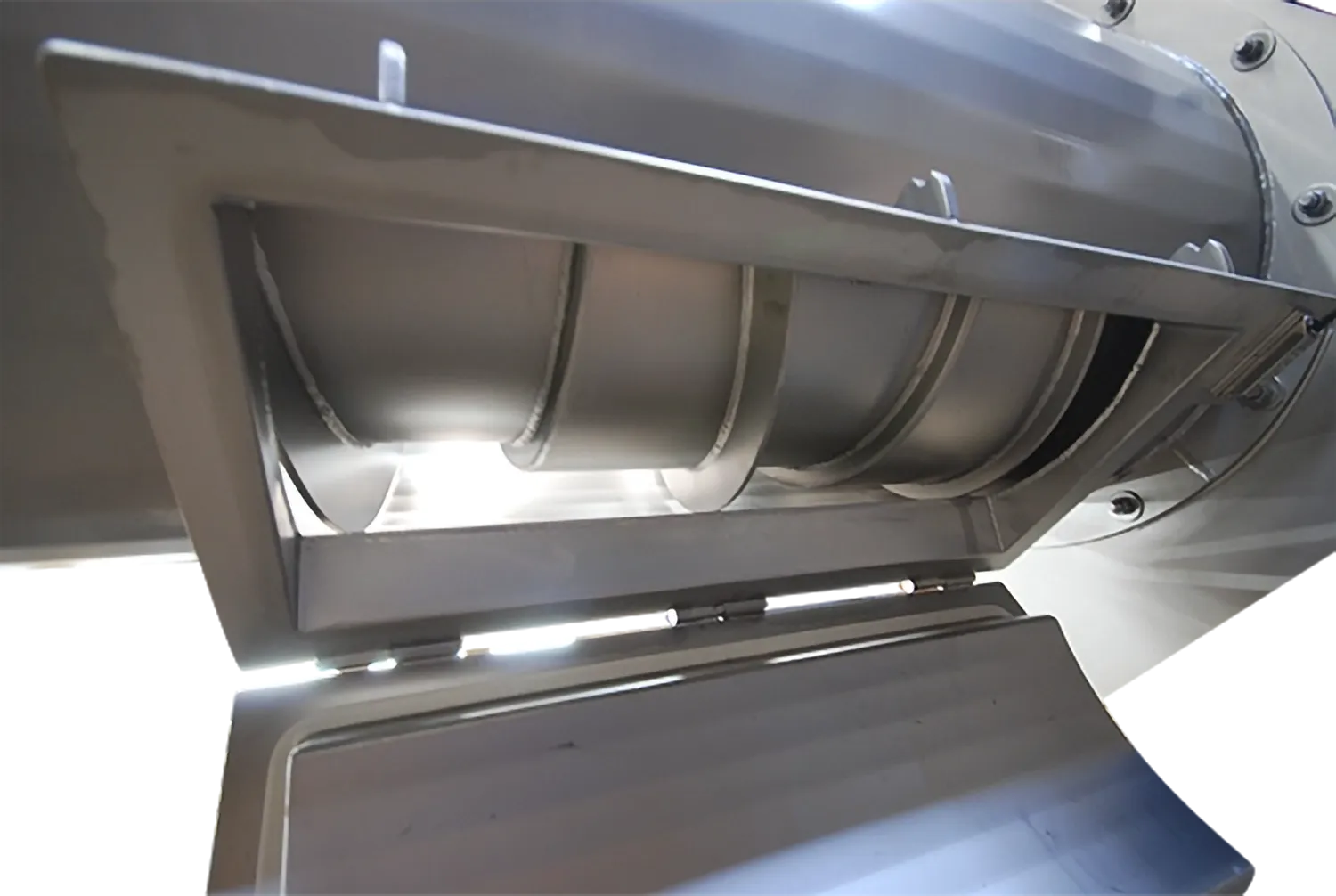
  • Variable pitch:
    By reducing the pitch of the screw flights toward the outlet, the intake rate of the product is gradually decreased. This prevents excessive material intake at the beginning of the screw and supports balanced flow.
  • Adjustment to bulk material characteristics:
    The choice of screw parameters must be aligned with the properties of the bulk material, such as cohesion, flow behavior, and bulk density.
  • Conical shaft core design:
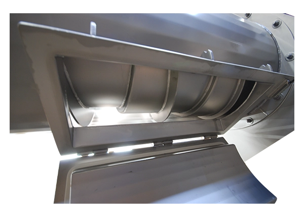
    An increasing core diameter (or shaft envelope) along the length of the screw results in a decreasing fill ratio, enabling more uniform discharge of the material. This prevents buildup and minimizes the risk of bridging in the silo.
  • Conically designed trough:
    By gradually increasing the trough width or height toward the outlet, product is evenly discharged per screw rotation along the entire inlet length — extracted from the silo/hopper as FIFO. This ensures uniform material movement and avoids undesired stagnation zones.
  • Adaptation to the silo outlet:
    The geometry and dimensions of the outlet opening play a major role in preventing stagnation zones and ensuring consistent material flow.
icon check

No dead zones in the storage vessel

icon check

Distribution of residence time (First In – First Out), FIFO

icon check

Low segregation during discharge to the process

icon check

No product aging due to even discharge

How can you dose a mass flow?

To achieve mass flow, a designer must ensure that during each screw shaft rotation, a uniform inflow along the entire inlet length is guaranteed. It’s not just about increasing the pitch along the inlet but also ensuring that an equal number of liters per rotation is fed in.

Mass flow creation can be approached in different ways. A common method is to design the shaft conically under the inlet — this can be done either internally or externally.

In an internally conical design, the shaft must be fitted with a cone beneath the inlet. In an externally conical design, the housing below the inlet must taper at the same conical angle as the screw flight itself.

A second method is to build the screw shaft under the inlet in a stepped manner, where the step and the pitch progression of the screw flight ensure a consistent inflow of volume per rotation.

Klinkenberg

We are happy to help Our company is ready every day to support your critical processes.

Request a quote

An Application of Mass Flow Dosing

p>For applications where it is important to generate a mass flow, the product column above the screw must descend evenly according to the FIFO principle. This is especially critical when a cooling/heating tower is positioned above the dosing screw. The goal is for the product to flow evenly along the cooling plates and be dosed into the discharge point of the screw. To make this possible, it is important that during every rotation of the screw shaft, an equal volume of product flows between the screw flights.


Applied Technologies We always select the right technology for your process

Klinkenberg technology includes the following variations:

image

Technology, finish and safety.

Would you like to know more about the underlying or applied technologiess for Screw Conveyors, such as the use of bearing systems, seals, safety, ATEX, or a desired surface finish?

Discuss the possibilities Discover more

Variants

Mass flow screw with cleaning hatch

image

Mass flow dosing under high pressure

 
image

Mass flow stepped screw shaft

image

Mass flow paddle discharge bottom

image

Documentation Exclusive with a personal design

FAQ Direct answers to your questions

Quickly find answers to frequently asked questions about Mass Flow Dosing. Our FAQ section helps you make the right choice.

Your question isn’t listed here?
Feel free to send us a message with your question.

Contact us

Mass flow dosing is a method where a constant and controlled amount of material per unit of time is fed into a process. This is done with a Dosing Screw that extracts and transports the material evenly.

Mass flow dosing continuously feeds material, whereas batch dosing processes a fixed quantity in separate portions. Mass flow dosing is ideal for processes that require a steady supply, such as mixing, drying, or combustion.

Capacity is influenced by screw diameter, pitch, rotational speed, and the properties of the material. Friction between the product and the screw wall also plays a role.

Through smart design with variable screw pitch and shaft diameter, material is extracted evenly. Additional tools like an agitator or vibrating bottom can be used to stimulate material movement.

Accuracy depends on screw speed, fill rate, material characteristics, and control technology. A frequency inverter allows precise adjustment of the screw speed.

Yes, but specially adapted dosing screws are needed, with special coatings, open pitch designs, or heated troughs to prevent buildup and clogging.

In the section below the silo, additional pressure is exerted on the product, resulting in a higher fill rate. This requires a robust drive system with sufficient torque to overcome the added resistance.

The speed is often controlled with a frequency inverter, allowing dynamic adjustment of the dosing capacity based on process needs.

Yes, dosing screws can be built according to ATEX guidelines with spark-free motors, pressure relief, and controlled dust extraction to minimize explosion risks.

Depending on the application, dosing screws can be made of steel, stainless steel (SS 304 or 316), or coated with wear-resistant or non-stick coatings such as PTFE or Hardox.